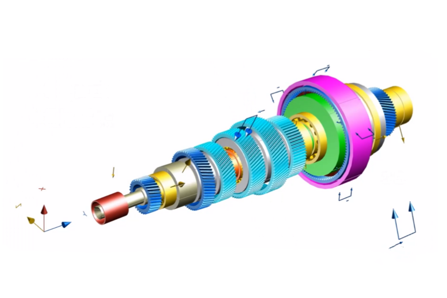
Gears are vital components in various mechanical systems, providing efficient power transmission, speed control, and motion synthesis. By delving into the basics of gear design, including considerations for gear parameters, design principles, and the functions of different gear systems, we will gain the valuable knowledge necessary for designing gears that exhibit optimal performance, reliability, and durability.
Advantages and disadvantages of gear transmission
Advantages: Gears offer several advantages, including a wide range of circumferential speed and power usage, precise transmission ratio, high mechanical efficiency, reliable operation, long lifespan, the ability to transmit power between parallel and intersecting shafts, and a compact structure.
Disadvantages: Requires high manufacturing and installation precision, resulting in higher costs; unsuitable for long-distance transmission between two shafts.
Characteristics of involute
- The length of the involute segment on the base circle is equal to the arc length traversed on the base circle.
- The normal at any point on the involute must be tangent to the base circle, and point N on the involute is the center of curvature, with line segment NK as its radius of curvature.
- cosαk = ON/OK = rb/rk. The pressure angle of each point on the involute is not equal. The larger the radius of curvature rk, the larger the pressure angle. The pressure angle on the base circle is zero.
- The shape of the involute depends on the size of the base circle. As the radius of the base circle increases, the corresponding radius of curvature on the involute also increases. The involute becomes a straight line when the base circle is infinitely large. Therefore, the tooth profile of the involute gear is a straight line, excluding the portion inside the base circle.
Gear meshing conditions
It is necessary to ensure that each pair of gears on the line of contact can enter the meshing state correctly: m1 = m2 = m (module) and α1 = α2 = α (pressure angle) are equal. The helical gears’ helix angles of the two wheels must be equal in magnitude but opposite in direction. For bevel gears, the cone distances of the two wheels must be equal. For worm gears, the lead angle of the worm must be equal to the helix angle of the worm wheel and have the same direction.
Conditions for continuous transmission of tooth profile
Overlap ratio ε = B1B2/ρb > 1 (the length of the actual line segment B1B2 is greater than the normal tooth pitch).
The basic law of tooth profile meshing
For a pair of tooth profiles in planar meshing, the common normal at their instantaneous contact points must intersect at the corresponding node C on the line of centers of the gears. This node divides the line of centers of the gears in a way that is inversely proportional to their angular velocities.
Root undercut
Cause: When using a rack-type tool (or a gear-type tool) to machine a gear, if the number of teeth on the gear is too small, the tooth top line of the tool will exceed the limit point of engagement on the gear blank. As a result, the tool will cut away a portion of the involute tooth profile at the root, leading to a root undercut.
Consequence: Root undercut in gears include weakening the gear root, reduced bending strength, and decreased overlap ratio.
Solution: A solution to mitigate root undercut in gears is the utilization of modified profile gears.
Advantages of positive shifted gear
- Modified profile gears enable manufacturing gears with fewer teeth than the minimum allowable number without experiencing root undercut, thereby reducing the size of the gear transmission structure.
- Appropriate modification can be applied to meet the requirements of the actual center distance.
- Improved bending strength of the smaller gear, thereby enhancing the overall strength of a gear pair.
Failure modes of gears
Failure modes of gears include Tooth fracture, tooth surface pitting, tooth surface adhesion, and tooth surface wear. The main failure modes for open gears are tooth surface wear and tooth fracture. The main failure modes for enclosed gears are tooth surface pitting and tooth fracture.
Gear Design Principles
The design calculations typically focus on ensuring the fatigue strength of tooth surface contact and root bending for commonly used gear transmissions.
Tooth profile selection
Spur gears have relatively poor smoothness, high impact, and noise levels, while helical gears provide smoother operation with reduced impact and noise, making them suitable for high-speed transmissions.
Functions of Gear Systems
- Achieving high transmission ratios (in reducers).
- Enabling variable speed and directional transmission (in automotive transmissions).
- Facilitating the synthesis and decomposition of motion (in differentials, automotive rear axles).
- Enabling compact and high-power transmissions (in main gearboxes for engines, planetary gearboxes).
Thank you for reading. Click here to read more articles about gear technology.


