During the design and development of gear transmission products, gear noise is a common and often challenging issue. In many cases, noise level is not only a matter of comfort—it is also an important indicator of machine health, design quality, and manufacturing precision.
In this article, I’d like to share an overview of where gear noise comes from, how it is measured, and how it can be effectively controlled.
I. Where Does Gear Noise Come From? Identifying the “True Sound Source”
Gear noise is rarely caused by a single factor. Instead, it is usually the result of multiple interacting sources, which can be broadly classified into three categories:
- Gear meshing itself
- Vibration of auxiliary components
- System resonance
1. Gear Meshing: The Primary Noise Generator
When gears transmit power, tooth-to-tooth contact is the dominant source of noise. Even with a well-designed gear set, small imperfections during meshing can still generate sound.
- Tooth profile errors
If the tooth surface is not smooth or the pitch is uneven, the meshing action becomes irregular. This is similar to a comb snagging on tangled hair—each contact creates a small impact, resulting in a “clicking” or “rattling” noise.
The noise frequency is directly related to rotational speed and tooth count. For example, a 20-tooth gear rotating at 10 revolutions per second produces a meshing frequency of 200 Hz.
- Meshing dynamics
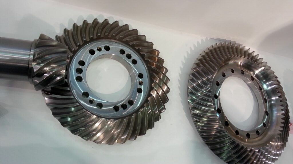
Even with perfect geometry, elastic deformation of the teeth during rotation causes fluctuations in contact force. This is why helical gears are generally quieter than spur gears—their tooth engagement is gradual rather than sudden, reducing impact and vibration.
- Insufficient lubrication
When the lubricant film between teeth is inadequate, metal-to-metal contact occurs, generating sharp noise and accelerating wear. This often leads to a vicious cycle: more wear causes more noise, and more noise indicates further damage.
2. Auxiliary Components: The “Accomplices” of Gear Noise
In addition to gears, supporting components such as bearings, couplings, and cooling fans can significantly contribute to overall noise.
- Bearing noise
Worn rolling elements or misaligned bearings typically generate high-frequency noise (100–3000 Hz), often perceived as a “hissing” sound.
At low speeds, intermittent knocking noises may indicate waviness on the bearing raceways.
- Coupling noise
Couplings connect the motor to the gearbox. Exposed bolts or rotating parts can create aerodynamic noise at high speeds. Misalignment may also induce vibration, indirectly amplifying gear noise.
- Auxiliary equipment noise
Cooling fans located too close to the housing can generate airflow noise, while turbulent oil flow or cavitation in lubrication pumps may produce gurgling sounds. These noises are often mistaken for gear-related issues.
3. System Resonance: The Noise Amplifier
In some cases, individual components may not be particularly noisy, but structural resonance dramatically amplifies sound levels.
- Structural resonance
If the natural frequency of the gearbox housing or base structure (for example, 500 Hz) coincides with the gear meshing frequency, vibration can be strongly amplified—much like pushing a swing at the right moment.
- Critical speed
When a rotating shaft reaches its critical speed, severe vibration may occur. This not only destabilizes gear meshing but can also excite the entire system, producing a loud and unpleasant roaring noise.
II. How Is Gear Noise Evaluated? Professional Measurement Practices
Evaluating gear noise should never rely solely on human hearing. Objective measurement and frequency analysis are essential.
1. Key Indicator: Sound Pressure Level (dBA)
Noise level is commonly expressed as A-weighted sound pressure level (dBA), which reflects the frequency sensitivity of the human ear. Humans are more sensitive to mid- and high-frequency noise (1000–4000 Hz), and A-weighting accounts for this characteristic.
- Reference standards
According to OSHA (Occupational Safety and Health Administration), the maximum permissible noise exposure is 90 dBA for 8 hours. Shorter exposure allows higher levels (e.g., 105 dBA for 1 hour). Peak impulse noise should not exceed 140 dB.
- Measurement instruments
Noise is measured using a sound level meter, classified as:
- Type 1: precision (laboratory use)
- Type 2: general-purpose (workshop and field use)
Calibration before measurement is essential to ensure accuracy.
2. Frequency Analysis: Locating the Noise Source
Overall noise level alone is insufficient. Frequency-domain analysis helps identify the dominant source.
- Octave band analysis
Sound is divided into frequency bands (63 Hz, 125 Hz, 250 Hz … 8000 Hz).
For example:
- High levels at 250 Hz often indicate low-speed gear meshing
- High levels at 1000 Hz may point to high-speed gears or bearing issues
- FFT analysis
Fast Fourier Transform (FFT) breaks complex noise into discrete frequencies.
If a prominent peak appears at 1060 Hz, and this matches the calculated meshing frequency of a high-speed gear stage, the primary noise source can be confidently identified.
3. Industry Practice: AGMA Noise Measurement
The gear industry commonly refers to ANSI/AGMA 6025-D98 for noise measurement.
- Test environment
Measurements are conducted in a semi-reverberant workshop environment, not in an anechoic chamber, to better represent real operating conditions. Background noise must be measured and subtracted from the total sound level.
- Microphone position
The microphone is placed perpendicular to the gearbox side surface, facing its center. Distance depends on gearbox size (typically 1 m for small gearboxes, 3 m for large ones), with a minimum height of 1 ft above the floor to reduce reflection effects.
- Operating condition
Gearboxes are tested under no load or light load. Light load helps eliminate backlash and ensures more stable measurement. Noise levels are recorded at normal operating speed and averaged if fluctuations occur.
III. How to Control Gear Noise? Managing Both Source and Transmission Path
The fundamental strategy for noise control is simple:
reduce noise at the source or block its transmission.
1. Design and Manufacturing Optimization: Source Control
This is the most effective and economical approach.
- Proper gear type selection
Helical gears and double-helical (herringbone) gears are preferred over spur gears. Their gradual engagement typically reduces noise by 5–10 dBA.
- Tooth modification and accuracy
Applying profile and lead modifications (such as tip relief) reduces initial contact shock. Improving manufacturing accuracy minimizes pitch and profile errors, directly lowering vibration.
- Speed and load control
Reducing pitch line velocity, when feasible, lowers noise. For applications with fluctuating loads, optimized tooth modifications help maintain stable meshing under varying conditions.
2. Component and Lubrication Improvements: Reducing Secondary Noise
- Bearings and shafting
Ensure proper alignment during installation. For high-speed applications, use low-noise, high-precision bearings. Dynamic balancing of shafts reduces runout and improves tooth contact stability.
- Lubrication system
Use higher-viscosity gear oils (e.g., ISO VG 460) to form a thicker lubricating film. Maintain proper oil level—too high causes churning noise, too low leads to insufficient lubrication.
- Auxiliary equipment optimization
Select low-resistance fan blades and maintain sufficient clearance from housings. Increase pump inlet and outlet diameters to reduce turbulent flow and prevent cavitation noise.
3. Blocking the Transmission Path: Preventing Noise Radiation
When source reduction is limited, controlling the transmission path becomes essential.
- Vibration isolation
Elastic mounts such as rubber pads or spring isolators reduce vibration transmission to foundations and surrounding structures, typically lowering high-frequency noise by 3–5 dBA.
- Sound insulation and absorption
Install acoustic barriers around gearboxes. Use metal panels for sound insulation and internal acoustic foam for absorption. Treat workshop walls and ceilings to reduce sound reflection.
- Full enclosure
For extremely high noise levels (above 100 dBA), a fully enclosed acoustic housing may be required. A combination of thick steel panels and internal sound-absorbing material can reduce noise by 10–20 dBA. Adequate ventilation and maintenance access must be carefully designed.
IV. Conclusion: The Core Logic of Gear Noise Control
Gear noise is not a single-point problem—it is the result of design, manufacturing, assembly, and operating conditions throughout the entire product lifecycle.
Effective noise control follows three key principles:
- Identify the source first: Use frequency analysis to determine whether noise originates from gear meshing, bearings, or resonance—avoid blind countermeasures.
- Prioritize source control: Improvements in gear design and manufacturing accuracy deliver the greatest benefits at the lowest cost.
- Match solutions to real applications: Use isolation and barriers in workshops, and full enclosures only when necessary. Absolute silence is rarely required—meeting functional and safety requirements is the real goal.
Thank you for reading. We are looking forward to serving you with our exceptional gear solutions. #BeyondGears
Read More: