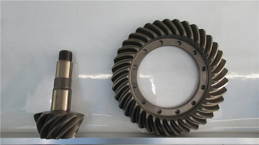
Spiral bevel gears, also known as helical bevel gears, play an indispensable role in the field of automotive drivetrains due to their smooth transmission. The traditional manufacturing and gear-cutting processes for spiral bevel gears rely on heat treatment deformation to meet gear design requirements, ensuring proper meshing of the active and passive gears. With advancements in gear manufacturing technology, post-heat treatment gear grinding has been employed to enhance gear tooth profiles, resulting in a significant improvement in gear accuracy and consistency.
In order to further improve the grinding efficiency of spiral bevel gears and enhance the quality of ground gear products, an experimental investigation is conducted to model the tooth grinding process. The experiment primarily focuses on the variations in tooth profiles (pressure angle, helix angle, and toe crown direction) as indicated by the 45-point metrology sheet, aiming to control and optimize the contact zone conditions.
Conclusions:
Through recent adjustments and production validations, preliminary conclusions have been drawn regarding the following scenarios:
- Error in the helix angle direction → Employing first-order reverse correction for the passive side and second-order reverse correction for the active side results in a qualified contact zone.
- Error in the pressure angle direction → Utilizing first-order reverse correction with pressure angle modification for the passive side, and employing second-order reverse correction with pressure angle modification reverse correction for the active side, achieves a qualified contact zone.
- Error in the toe crown direction → Applying first-order reverse correction with pressure angle modification option and grinding wheel diameter correction for the passive side. For the active side, employing second-order reverse correction with pressure angle modification option and grinding wheel diameter correction reverse correction results in a qualified contact zone.
- Comprehensive error (including helix angle, pressure angle, and toe crown mixed error) → Applying first-order reverse correction with “grinding wheel three-item” modification for the passive side. For the active side, employing second-order reverse correction with “grinding wheel three-item” modification reverse correction results in a qualified contact zone (the grinding wheel three-item option is enabled in the product design).
Examples:
Specific examples are as follows:
① When a single pressure angle direction error occurs, the passive side utilizes first-order reverse correction (Spiral Ang-Cross, Spiral Ang-Toe/Heel, Pres Ang-Lameness) along with pressure angle (Pres Angle-IB, Pres Angle-OB) modification options for reverse correction. On the active side, second-order reverse correction (Spiral Ang-Cross, Spiral Ang-Toe/Heel, Pres Ang-Lameness, Pres Ang-Top/Flank, Helical Motion) is applied along with pressure angle (Pres Angle-IB, Pres Angle-OB) modification options for reverse correction.
The concave surface measurement sheet indicates an excessive pressure angle.
Convave Fa=10.09′
Selecting the reverse correction options Spiral Ang-Cross, Spiral Ang-Toe/Heel, Pres Ang-Lameness, Pres Angle-IB, Pres Angle-OB.
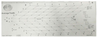
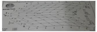
Measurement inspection sheet before adjustment, as shown in Figure 1.
Output Reverse Correction Sheet.
With the above parameters input into the machine tool, the gears were reground after regrinding the grinding wheel. Upon remeasurement, the results are obtained as shown in Figure 3.
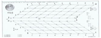
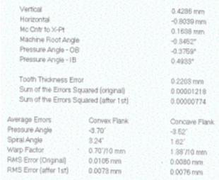
Measurement inspection sheet after reverse correction, as shown in Figure 3.
The concave surface measurement sheet indicates that the pressure angle has been corrected.
Convave Fa=1.08′
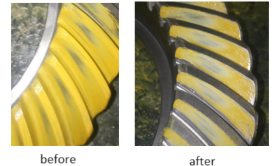
Engagement contact zone using the same active gear for rolling inspection before and after gear adjustment, as shown in Figure 4.
② When there is a significant difference in the toe crown amount, the passive side utilizes first-order reverse correction (Spiral Ang-Cross, Spiral Ang-Toe/Heel, Pres Ang-Lameness) along with pressure angle modification (Pres Angle-IB, Pres Angle-OB) and grinding wheel diameter (Cutter Radius) correction options for reverse correction. On the active side, second-order reverse correction (Spiral Ang-Cross, Spiral Ang-Toe/Heel, Pres Ang-Lameness, Pres Ang-Top/Flank, Helical Motion) is applied along with pressure angle modification (Pres Angle-IB, Pres Angle-OB) and grinding wheel diameter (Cutter Radius) correction options for reverse correction.
The measurement sheet indicates a convex side short and a concave side long in the contact zone.

Figure 6: Contact zone before reverse correction.
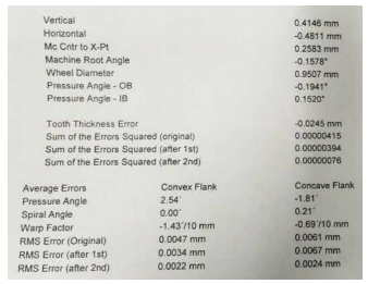
Figure 7: Output Reverse Correction Sheet.
Engagement contact zone using the same active gear for rolling inspection after gear adjustment, as shown in Figure 8.


Figure 9: Measurement inspection sheet after reverse correction.
③ When there is a significant difference in the contact zone or measurement sheet from the sample (or includes mixed errors of helix angle, pressure angle, and toe crown), the passive side utilizes first-order reverse correction (Spiral Ang-Cross, Spiral Ang-Toe/Heel, Pres Ang-Lameness) along with grinding wheel three items (Cutter Radius, Profile Curvature IB, Profile Curvature OB) for reverse correction. On the active side, second-order reverse correction (Spiral Ang-Cross, Spiral Ang-Toe/Heel, Pres Ang-Lameness, Pres Ang-Top/Flank, Helical Motion) is applied along with grinding wheel three items (Cutter Radius, Profile Curvature IB, Profile Curvature OB) for reverse correction.
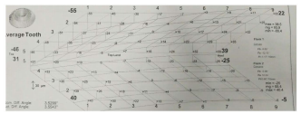
Figure 10: Measurement inspection sheet before reverse correction.
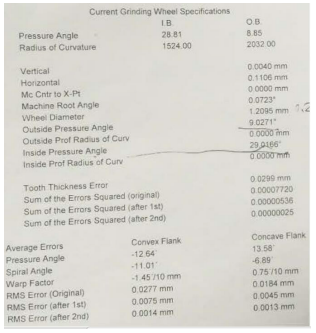
Figure 11: Output Reverse Correction Sheet.

Figure 12: Measurement inspection sheet after reverse correction.
The experiment indicates that it is feasible to control the engagement contact zone of the active and passive gears through a 45-point measurement inspection sheet. To achieve the desired tooth profile and obtain ideal contact imprints after gear engagement, it is necessary to determine the appropriate reverse correction options through the above-mentioned method.
Thank you for reading this article, and we look forward to serving you with our exceptional gear solutions. #BeyondGears
Read more: