Shaft Parts in Machinery Products
Shaft parts are common components widely used in machinery. The working capability and quality of machines are largely dependent on shafts. If a shaft fails, it may lead to serious consequences. Shafts are among the most critical mechanical components, serving as the primary part of a shaft system, supporting attached parts, and transmitting motion and power. To ensure that the components mounted on the shaft are properly positioned and secured, and to meet processing and assembly requirements, it is essential to determine the shape and structural dimensions of different shaft sections through structural design.
Overview of Shaft Parts Processing
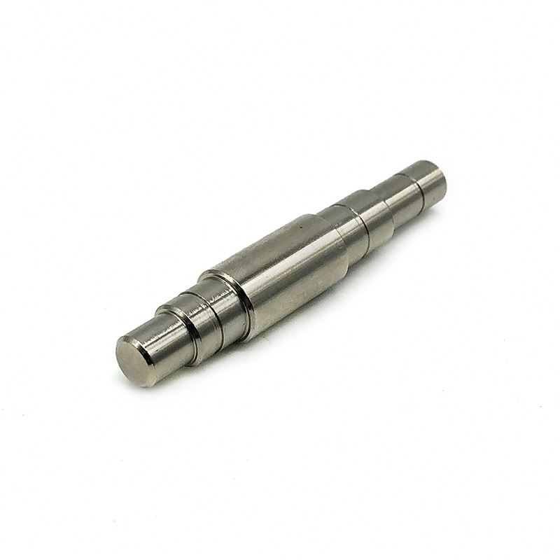
A shaft is a cylindrical object positioned within bearings, wheels, or gears, though some shafts are square in shape. It supports rotating parts and rotates along with them to transmit motion, torque, or bending moments. Generally, shafts are metal rods with varying diameters in different sections. Rotating machine components are typically mounted on shafts.
Shaft Classification
Shafts can be categorized based on their axis shape into crankshafts and straight shafts. Based on their load-bearing characteristics, they can be further classified into:
- Rotating shafts
- Spindles
- Transmission shafts
Considerations in Shaft Structural Design
The structural design of a shaft involves determining its external shape and dimensions. This process depends on factors such as the type, size, and position of mounted components, fixing methods, the nature and distribution of loads, bearing types and sizes, material selection, manufacturing and assembly processes, installation, transportation, and deformation concerns. Designers should tailor the shaft structure to specific requirements and, if necessary, compare multiple design alternatives to select the optimal solution.
General Principles of Shaft Structural Design
- Key Design Aspects Shaft design involves material selection, structural design, performance design, and precision design. The goal is to establish a reasonable external shape and complete dimensions. Since shafts work together with their mounted components (including supporting bearings) to form a shaft assembly, their design must accommodate component positioning, fixing, adjustments, assembly, and disassembly.
- Performance Design This primarily includes strength and rigidity design. The first step is to simplify the mechanical model (often reducing it to a simply supported beam or cantilever beam based on support conditions). Next, failure modes are identified based on load type and working conditions, and suitable design criteria are applied. Performance criteria include strength and rigidity considerations. High-speed shafts also require vibration stability analysis to prevent excessive vibrations or resonance.
- Precision Design This includes dimensional tolerances and geometric tolerances to ensure proper function.
Shaft Materials and Selection
- Common Shaft Materials The primary materials used for shafts are carbon steel and alloy steel. Common carbon steel includes 45 steel, which is often normalized or quenched and tempered to enhance mechanical properties. Alloy steel provides higher strength and better heat treatment performance but is more sensitive to stress concentrations and is expensive. Therefore, it is used in applications requiring high speed, heavy loads, wear resistance, or extreme temperature conditions. However, since alloy and carbon steels have similar elastic modulus values at room temperature, using alloy steel does not significantly improve shaft stiffness.
- Material Selection Based on Load and Performance Requirements
- For high-load, high-strength, compact, or wear-resistant shafts, alloy steels such as 40Cr, 20Cr, and 35SiMn are commonly used.
- For complex shapes like crankshafts and camshafts, materials like cast steel or ductile iron are often chosen due to their vibration-damping properties, lower stress concentration sensitivity, and cost-effectiveness.
Design Requirements for Shaft Parts
Based on their function and working conditions, the design requirements for shaft parts mainly focus on the following aspects:
- Dimensional Accuracy
- Bearing journal (supporting journal): Requires high precision (typically IT5–IT7) to determine shaft positioning and provide support.
- Fitting journal (for gears, pulleys, etc.): Requires slightly lower precision (IT6–IT9).
- Geometric Accuracy
- Includes roundness, cylindricity, and taper accuracy for key surfaces such as bearing journals and cone surfaces.
- Precision shafts may have additional geometric tolerance requirements in engineering drawings.
- Positional Accuracy
- Includes coaxiality, radial runout, perpendicularity of key surfaces, and parallelism of end faces.
- Surface Roughness
- Bearing journals: Typically 0.2–1.6 μm
- Fitting journals: Typically 0.4–3.2 μm
- Additional Requirements
- Heat treatment, chamfering, deburring, and appearance finishing may be specified based on functional needs.
Heat Treatment of Shaft Parts
- Medium Carbon and Medium Carbon Alloy Steels
- Common choices include 35, 40, 45, 50, 40Cr, 40CrNi, and 40MnB.
- These materials are typically normalized or quenched and tempered to enhance overall mechanical properties.
- For wear resistance, surface hardening may be applied to bearing journals.
- Carburized and Nitrided Steels for High-Strength Applications
- 20Cr and 20CrMnTi are commonly used for carburized shafts, undergoing carburization, quenching, and low-temperature tempering to improve wear resistance and toughness.
- For Low-Stress or Non-Critical Shafts
- Standard carbon steels such as Q235–Q275 may be used.
- For Complex Shafts Like Crankshafts
- Ductile iron and high-strength gray iron are preferred due to their ease of manufacturing, vibration absorption, and stress distribution characteristics.
Shaft Processing Technology and Key Considerations
Shaft machining is a fundamental skill in lathe work. However, students often struggle to achieve high-quality finished parts due to inadequate process planning. The machining process plan directly affects part quality, production efficiency, and economic viability.
Key Points in Machining Process Planning
- Understanding the Part Drawing
- Analyze structural features, precision, material, and heat treatment requirements.
- Review assembly drawings, component assembly drawings, and acceptance standards.
- Typical Process Flow for Carburized Shafts
- Cutting → Forging → Normalizing → Rough Machining → Semi-Finishing → Carburizing → Decarburization Processing (if needed) → Quenching → Threading/Drilling/Milling → Rough Grinding → Low-Temperature Aging → Semi-Finish Grinding → Low-Temperature Aging → Finish Grinding
- Selection of Reference Surfaces
- Rough Reference:
- If non-machined surfaces exist, they should be used as rough reference surfaces.
- For fully machined shafts, alignment should be based on minimum machining allowance.
- Choose smooth, flat surfaces for alignment while avoiding gating points.
- Fine Reference:
- Follow the coincidence principle, using design or assembly references whenever possible.
- Maintain consistent reference points across multiple machining steps.
- Ensure stability and precision during installation.
- Rough Reference:
- Optimizing Process Design
- The chosen machining method directly impacts part quality, efficiency, and costs.
- The most rational processing method should be selected based on available equipment, production scale, and other practical considerations.
- Whenever possible, advanced machining techniques should be used to improve production efficiency and product quality.
Thank you for reading. We are looking forward to serving you with our exceptional gear solutions. #BeyondGears
Read More: